# ESP8266
【古い-転載記事】
# 概要
低価格のWi-Fiモジュール(EPS8266)を使用した機器関連のカテゴリーです。
【古い-転載記事】
# EPS8266関連
低価格のWi-Fiモジュール(EPS8266)を使用した機器関連のカテゴリーです。
EPS8266モジュールを搭載した特に「ESP-WROOM-02」モジュールは低価格でWi-Fiネットワークに簡単に接続できます。ちょっとセンサーを付けて結果をサーバーにPostしてデータを取りたいというシンプルな事が1,000円前後で可能になります。
作成日時 2016-04-14 01:09 更新日時 2016-05-09 19:49
# FTDIドライバー
# FTDIドライバー
##### FTDIドライバー
EPS8266をOS X El capten 上のArduionで開発するときシリアルモニタへ「Serial.print/Serial.print」で出力すると、途中で出力されなくなってしまう問題に遭遇したので、そのテスト結果と対処方法をまとめました。
作成日時 2016-05-09 19:20 更新日時 2016-05-10 12:,09
---
##### 【現象】
EPS8266をAdruinoで開発するときにいろんなメッセージをシリアルモニタへ「Serial.print/Serial.print」で出力していたのですが、その出力結果が次のように途中で出力されなくなってしまう状態に遭遇しました。
##### 【動作環境】
PC側
・MacPro 2013 (OS X 10..4.11 (15E65))
Arduino 側
・Arduino SDK (Arduino 1.6.8)
・EPS-WROOM-02 ボード
##### 【出力例】
異常な出力例と正常な出力例を示します。
シリアルモニタへは本来は「------」の後に「setup() start」と続き、最後の「------ setup() end ------」で出力されるのです。ところが、何故か途中でシリアルモニタへの出力が途切れてしまっています。プログラムに問題が発生して例外で止まっているとかではなく、プログラムは正常に動作しているようでシリアルモニタへの出力が出ていない状況です。
\--- 異常な出力例 --- ここから
\[\[ LED Chika 2016-05-08 19:19 A10 Objs.,Inc. \]\]
\------
->>-- ここまで
\--- 正常な出力例 --- ここから
\[\[ LED Chika 2016-05-08 19:19 A10 Objs.,Inc. \]\]
------ setup() start ------
print test 01
print test 02
print test 03
print test 04
print test 05
print test 06
print test 07
print test 08
print test 09
print test 10
------ setup() end ------
->>-- ここまで
# テスト結果
##### 【概要】
最初は、ハードウエアとかソフトウエア(SDK)の不備などを疑って、EPS8266搭載ボードを交換したり、USBのシリアル通信ハードを変えたり、Arduinoの出力プログラムを修正したり、SDKのバージョンを変えて問題を回避しできないかと試みていました。しかし、一向に問題を解決出来ませんでした。
また、試しにArduino UNO R3 (arduino.cc製)に接続したところ問題無く出力しています。
これまでは、OS X El captenになってからアップル社製FTDIドライバーのみで開発して来ました。特に問題が無かったのですが、試しにFTDI chipsのFTDIドライバー(Mac OS X 10.9 and above/ 2015-04-15/ version 2.3)と入れ替えたところ問題無く出力できるようになりました。ドライバーの問題か?、ということで、次のパターンでシリアルモニタへの出力テストをしてみました。
##### 【テスト結果】
========================
使用ボード: EPS-WROOM-02 開発ボード (スイッチサイエンス社製)
[ https://www.switch-science.com/catalog/2500/](https://www.switch-science.com/catalog/2500/)
ボード上のシリアルIF-IC: FT231XS (on Borad)
\*\*\*\*\*\*\*\*\*\*
使用ドライバー: com.FTDI.driver.FTDIUSBSerialDriver
シリアル結果
説明:
・全て正しく出力
\[\[ LED Chika 2016-05-08 19:19 A10 Objs.,Inc. \]\]
------ setup() start ------
print test 01
print test 02
print test 03
print test 04
print test 05
print test 06
print test 07
print test 08
print test 09
print test 10
------ setup() end ------
\*\*\*\*\*\*\*\*\*\*
使用ドライバー: com.apple.driver.AppleUSBFTDI
シリアル結果
説明:
・途中で途切れる
・プログラムのダウンロードと実行は行われているようだ
\[\[ LED Chika 2016-05-08 19:19 A10 Objs.,Inc. \]\]
\------
========================
使用ボード: Board1 ver.1.0 (KURAHASHIYA製)
[ https://www.switch-science.com/catalog/2696/](https://www.switch-science.com/catalog/2696/)
[http://jiwashin.blogspot.jp/p/esp-wroom-02-board1.html](http://jiwashin.blogspot.jp/p/esp-wroom-02-board1.html)
シリアルIF-IC: FT232RL
USBシリアルIF: 秋月電子通商 FT232RL USB シリアル変換モジュール
[http://akizukidenshi.com/catalog/g/gK-01977/](http://akizukidenshi.com/catalog/g/gK-01977/)
\*\*\*\*\*\*\*\*\*\*
使用ドライバー: com.FTDI.driver.FTDIUSBSerialDriver
シリアル結果
説明:
・全て正しく出力
\[\[ LED Chika 2016-05-08 19:19 A10 Objs.,Inc. \]\]
------ setup() start ------
print test 01
print test 02
print test 03
print test 04
print test 05
print test 06
print test 07
print test 08
print test 09
print test 10
------ setup() end ------
\*\*\*\*\*\*\*\*\*\*
使用ドライバー: com.apple.driver.AppleUSBFTDI
シリアル結果
説明:
・途中で途切れる
・プログラムのダウンロードと実行は行われているようだ
\[\[ LED Chika 2016-05-08 19:19 A10 Objs.,Inc. \]\]
\------
========================
使用ボード: Arduino UNO R3 (arduino.cc製)
[https://www.arduino.cc/en/main/arduinoBoardUno](https://www.arduino.cc/en/main/arduinoBoardUno)
https://www.switch-science.com/catalog/789/
シリアルIF-IC: Atmega16U2 (on Borad)
\*\*\*\*\*\*\*\*\*\*
使用ドライバー: com.FTDI.driver.FTDIUSBSerialDriver
シリアル結果
説明:
・全て正しく出力
\[\[ LED Chika 2016-05-08 19:19 A10 Objs.,Inc. \]\]
------ setup() start ------
print test 01
print test 02
print test 03
print test 04
print test 05
print test 06
print test 07
print test 08
print test 09
print test 10
------ setup() end ------
\*\*\*\*\*\*\*\*\*\*
使用ドライバー: com.apple.driver.AppleUSBFTDI
シリアル結果
説明:
・全て正しく出力
\[\[ LED Chika 2016-05-08 19:19 A10 Objs.,Inc. \]\]
------ setup() start ------
print test 01
print test 02
print test 03
print test 04
print test 05
print test 06
print test 07
print test 08
print test 09
print test 10
------ setup() end ------
========================
【対処方法】
・EPS8266使用をしたOS X El capten上のArduion開発環境でシリアルモニタの
出力には当面の間、次のドライバーを使用する事にしました。
FTDI chipsのFTDIドライバー(Mac OS X 10.9 and above/ 2015-04-15/ version 2.3)
[http://www.ftdichip.com/Drivers/VCP.htm](http://www.ftdichip.com/Drivers/VCP.htm)
# テストコード
```c++
/*
* Lチカ Arduion
*
*
* このスケッチは。Arduinoの基本テスト用
*
* 動作確認済みボード一覧
* https://en.wikipedia.org/wiki/List_of_Arduino_boards_and_compatible_systems
*
* Arduion UNO R3 __AVR_ATmega328P__
* EPS8266
*
*
*/
#include
#if defined(__AVR_ATmega328P__)
#else
#include
#endif
/*
* アプリケーション情報
*/
#define appName "LED Chika"
#define appDates "2016-05-08 19:19"
#define appInitMsg "A10 Objs.,Inc."
void printAppInfo () {
Serial.println("");
Serial.println("");
Serial.print(" [[ ");
Serial.print(appName);
Serial.print(" ");
Serial.print(appDates);
Serial.print(" ");
Serial.print(appInitMsg);
Serial.println(" ]]");
Serial.println("");
}
/*
* 各種定義
*/
// PIN 定義
#if defined(__AVR_ATmega328P__)
const int PORT_LED = 13;
#else
const int PORT_LED = 13;
#endif
// 通信 定義
volatile static long serialPortSpeeds = 115200; // PCのシリアルポートのスピード 921600 or 115200 or 74880
// LED 点滅スピード
volatile static long LEDflashingSpeed = 100; // ms
/*
* 初期化
*/
void setup() {
// put your setup code here, to run once:
Serial.begin(serialPortSpeeds);
printAppInfo();
Serial.println("------ setup() start ------");
Serial.println("print test 01");
Serial.println("print test 02");
Serial.println("print test 03");
Serial.println("print test 04");
Serial.println("print test 05");
Serial.println("print test 06");
Serial.println("print test 07");
Serial.println("print test 08");
Serial.println("print test 09");
Serial.println("print test 10");
pinMode(PORT_LED,OUTPUT);
Serial.println("------ setup() end ------");
}
/*
* メインループ
*/
void loop() {
// put your main code here, to run repeatedly:
digitalWrite(PORT_LED,HIGH);
delay(LEDflashingSpeed);
digitalWrite(PORT_LED,LOW);
delay(LEDflashingSpeed);
}
```
# 電源まわりのテストなど(途中版)
【古い-転載記事】
# 概要
電源まわりのテストなど(途中版)
電源まわりで気になったことを書いてます。
EPS8266を使用したボードの電源関係をいじった内容です。
**注意**: この内容は、テストも記事も途中です。また、不定期に内容が更新されます。
**注意**: 消費電流を測定した内容を追加予定です。
更新履歴:
2016-04-22 01:30 最初の公開
作成日時 2016-04-22 01:04 更新日時 2018-06-16 04:41
# 基本構成
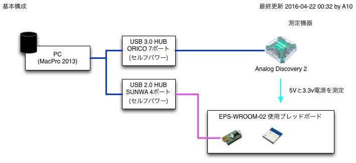
##### 基本構成
次のような構成でテスト
MacPro 2013
OS X 10.11.4
WaveForme 2015
[](https://book.a10-objects.jp/uploads/images/gallery/2026-04/1461254885.jpg)
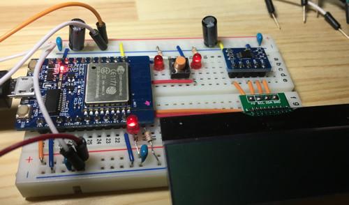
- ブレッドボードTYPE-A
USBシリアルIF: (ESP-WROOM-02開発ボードに組み込み)
EPS-WROOM-02: スイッチサイエンス ESP-WROOM-02開発ボード
[https://www.switch-science.com/catalog/2500/](https://www.switch-science.com/catalog/2500/)
- LEDをいくつか: 1つだけ10msでOn/Offを繰り返す(Arduinoコードを参照)
- LCDディスプレイ: 未使用
- 温度センサー: 未使用
[](https://book.a10-objects.jp/uploads/images/gallery/2026-04/1461254919.jpg)
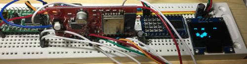
- ブレッドボードTYPE-B
USBシリアルIF: 秋月電子通商 FT232RL USB シリアル変換モジュール
[http://akizukidenshi.com/catalog/g/gK-01977/](http://akizukidenshi.com/catalog/g/gK-01977/)
EPS-WROOM-02: Board1 ver.1.0
[https://www.switch-science.com/catalog/2696/](https://www.switch-science.com/catalog/2696/)
[http://jiwashin.blogspot.jp/p/esp-wroom-02-board1.html](http://jiwashin.blogspot.jp/p/esp-wroom-02-board1.html)
- 4\*4 LEDマトリックス: 未使用
- 128\*32 OLED: 未使用
[](https://book.a10-objects.jp/uploads/images/gallery/2026-04/1461254950.jpg)
# テストプログラム (Arduino)
```c++
#include
#include
#include
#define appDates "2016-04-17 01:39"
#define appInitMsg "A10 Objs.,Inc."
volatile static int serialPortSpeeds = 115200; // PCのシリアルポートのスピード 921600 or 115200
volatile static bool serialPortOutput = true; // PCのシリアルポート出力設定 false:off, true:ON
// PIN 定義
const int PORT13_LED = 13;
// 変数 定義
Ticker ledTicker;
void setup() {
// put your setup code here, to run once:
setupLEDBlink();
/*
* WiFi.mode(m): set mode to WIFI_AP, WIFI_STA, WIFI_AP_STA or WIFI_OFF.
*/
WiFi.mode(WIFI_AP); //
}
void loop() {
// put your main code here, to run repeatedly:
}
// ********* LED Blink 関連 ******************************************
void setupLEDBlink() {
pinMode(PORT13_LED,OUTPUT);
digitalWrite(PORT13_LED,HIGH);
ledTicker.attach(0.1, blinkLED); // 割り込み設定 & 処理開始
}
void blinkLED() {
if(serialPortOutput) Serial.println("ledTicker: blinkLED");
int nextPinValue = LOW;
nextPinValue = (digitalRead(PORT13_LED) == HIGH)? LOW: HIGH;
digitalWrite(PORT13_LED,nextPinValue);
}
```
# テスト
##### テスト条件1 : USB 2.0 バスパワーのみで動作
USB 2.0 セルフパワー対応 4ポートハブ
SUNWA SUPPLAY 型番: USB-HTV410W
ブレッドボードTYPE-A
##### テスト条件1-結果
[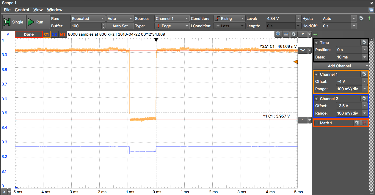](https://book.a10-objects.jp/uploads/images/gallery/2026-04/1461255316.png)
[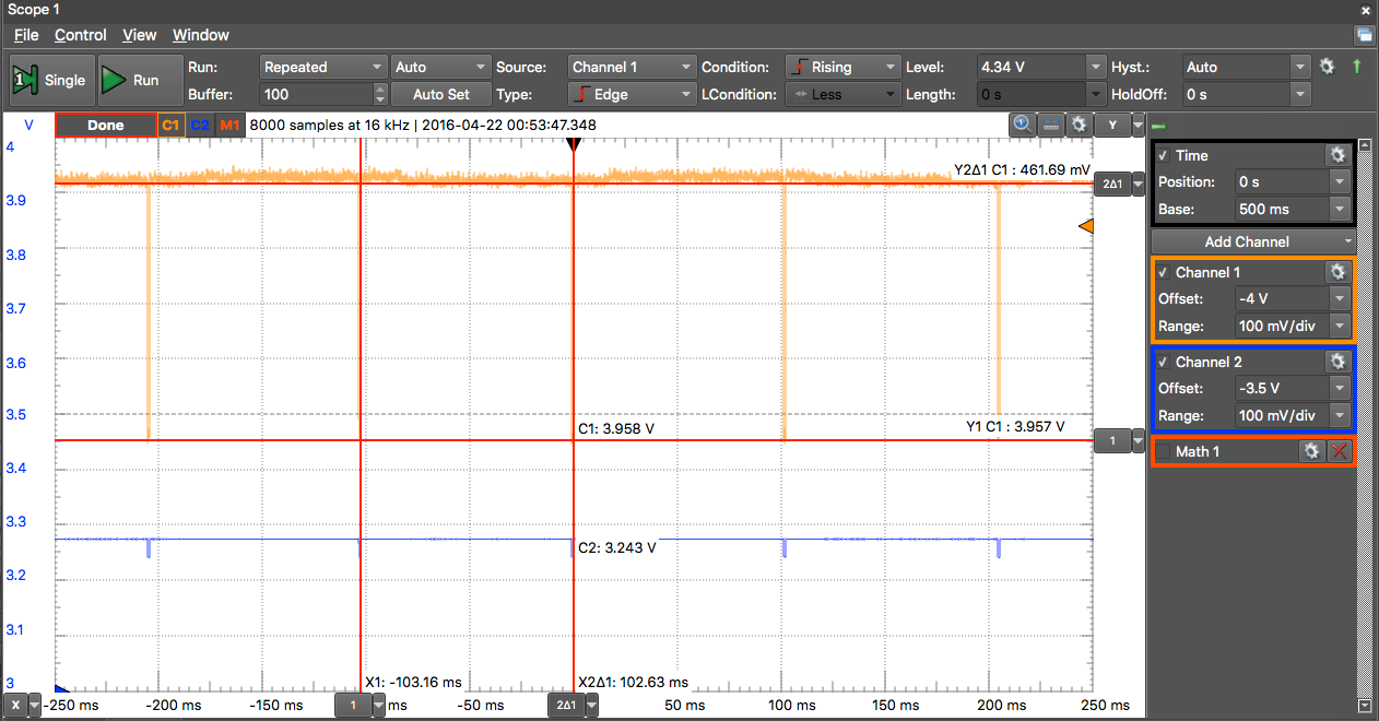](https://book.a10-objects.jp/uploads/images/gallery/2026-04/1461255330.png)
5vラインは、約4.4vです。
電圧降下はピークで約460mV、周期は約100ms(Wi-Fiモード時)。
##### テスト条件2 : USB 2.0 セルフパワー電源で動作
「テスト条件1 : USB 2.0 バスパワーのみで動作」と異なるのは、セルフパワー用の電源を接続したのみです。
ブレッドボードTYPE-A
##### テスト条件2-結果
[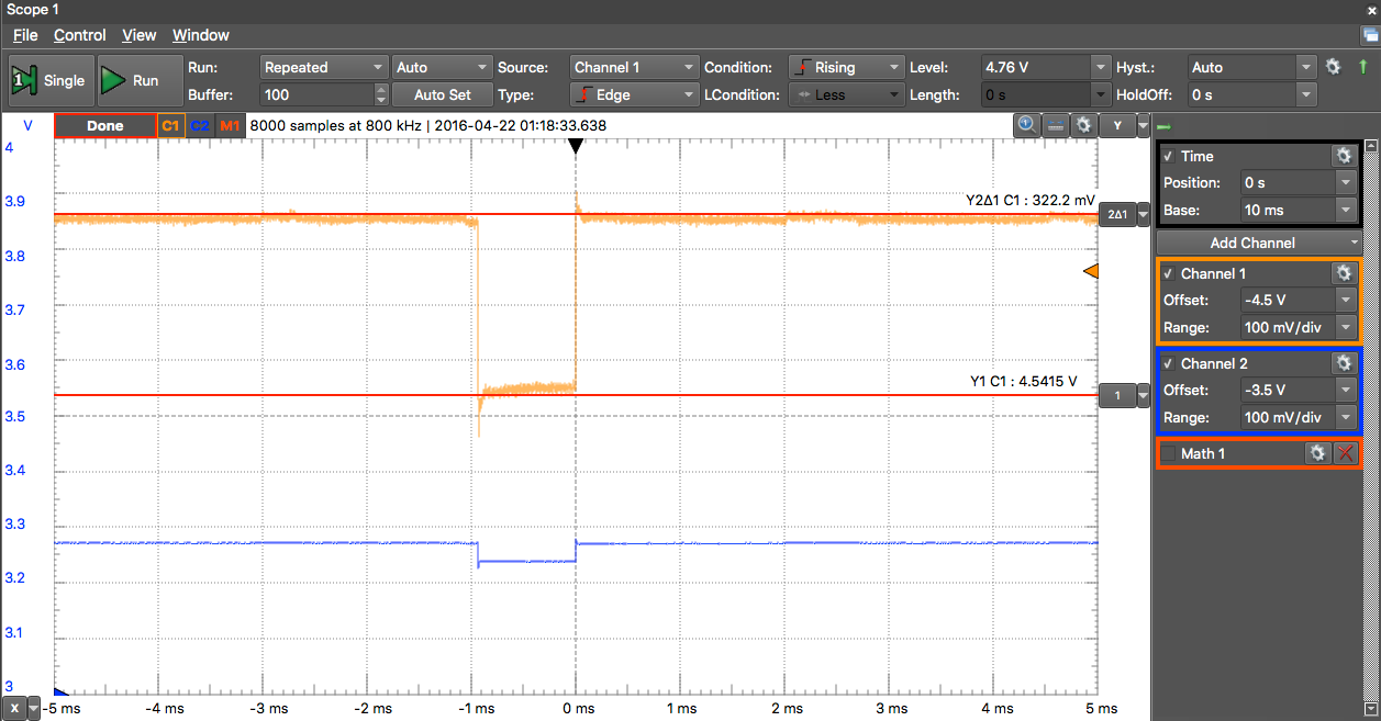](https://book.a10-objects.jp/uploads/images/gallery/2026-04/1461255982.png)
5vラインは、約4.86v程度です。
バスパワー時と比べて若干高めです。
電圧降下はピークで約320mV、周期は約100ms(Wi-Fiモード時)で、周期はプログラムが同じなのでパスワート同じです。。
このときの電圧をマルチメータで測定すると次の通りです。
[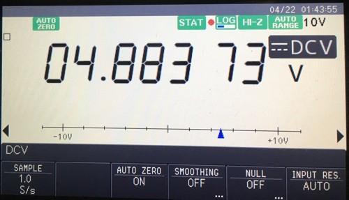](https://book.a10-objects.jp/uploads/images/gallery/2026-04/1461257732.jpg)
ここまでの測定結果として入力電圧が変化した時の電圧降下の関係は次の通りです。
(あまり参考にはならない?)
約4.4v -> 約460mV
約4.86v -> 約320mV
約4.9v -> 約230mV
なんか、5vラインの電力供給能力に左右されている?